2013/02/26

2009 September 18 - 24


8-) 2009 September 18  (7 of 35)


He! He! He!
my points have arrived, and I ordered the underlay. Its time to lay some track. (also have about 40 m at hand to start with)
Going to build the first BG Station (Wangarroo) and run up through the helix up to the top level, along the long wall, around the back and into the new centre island, where it will connect to the old Trentham layout, which will be lifted into the upper level in a few days. Trentham will continue on and swing left along back wall to other side wall and enter a dead end terminus, which Tony K of McKenzie and HO lLand has taken possession of.
I was having a problem sorting out the branch, and now I am particularly happy with the way it has worked out.
Cheers
Rod

Continues

Who would like a Victorian Rail Motor from China?
Rumours are around that Auscision will announce a new project in about 6 months.
It is said to be a 280 Walker with blue roof. Not sure if it will have a trailer, but if you want one, e mail Auscision and encourage them to build the model. They have received the engineering drawings and are very happy with them.
However can they sell enough to make it worth their while?
I want 2 :D
Cheers
Rod

ps eureka have caused some minor problems, reserving the 153 and 102 hp Walkers with the factory. The 280 has been accepted by China as a different model. However it will be silly for Eureka to go ahead after the 280 arrives. The 280 shares common parts with the smaller versions, as far as I know.

2009 September 23

The points arrived, but they were narrow gauge! We sent them back, and when they rang me, I went down and found they were large radius straights instead of curved :(
Still waiting..... :roll:
However I have started laying track around the first level of the helix, as well as the double track storage siding. Slight re-arrangement of the points at the station throat to accommodate the widest possible curve into the storage loop and helix, and just maybe we will have something to take a picture of, next Saturday.
Tony K is visiting, again, on Friday, so hopefully I will have about 30 m of operable track to test our A Class's out on. This underlay works really well too.
Have any of you guys used End of the Line Hobbies in Victor Harbour SA? What a nice bunch of people they are. Honest prices, kit building service, and good stocks of Peco, I highly recommend them to you, if you require mail order or particularly if you are local.
08 85527900 End of Line Hobbies

Cheers
Rod
2009 September 24

So here I am sitting here 18 working hours into my track laying session and only two points and two lengths of track glued in :cry:
Well I guess its not all that bad, however it occurred to me as I was laying the first point, that I needed to drill a hole for the point motor. Good thinking! Then I thought, "Hold on, I have never laid track for DCC before, and is there anything I need to do different in DCC to DC?"
So I read the blurb Peco writes in the instructions, and found it did not help much!
So then I googled Peco and DCC, and found this site... Welcome to the website that coined the phrase "DCC Friendly!" Thank goodness I did.
So now I have to remove shunts and make new ones to sort out the Peco Electrofrogs and modify the few insulfrogs that I am going to use as well.
AS an example, this is what Alan says about Electrofrogs

Peco "Electrofrog" Turnout Is DCC Friendly In Just a Few Snips.
Code 75, 83, 100:
The Peco turnout is a clever design. It can be a typical power routed turnout or a DCC friendly one. It is proof positive that manufacturers can make turnouts that suit all modellers' needs without it costing more to make them.
Let this be a public thank you on behalf of all model railroaders for a company responding to the needs of those who buy your product - by choice and because modellers like it, not because it is the least evil on the market.
This is a great improvement. The problem with the frog shorting is completely eliminated with no serious cutting effort on the part of the modeller required. Not only does not modeller not need to saw on the turnout, potentially risking damage, but also the jumpers around the frog do not need to be cut.
The only jumpers that need to be cut are those shown. Be careful not to cut those across the frog!
You have less problem of a dead frog with this arrangement. Furthermore, the desire to use a light bulb is drastically reduced.
I am also told that powering the frog is now provided by some wires (in some form since I have not yet seen this turnout) that come out the side. It sounds like the old Atlas/Roco that was an excellent turnout.
Congratulations Peco! 


How to Wire This Turnout:
This section assumes you have read "How to Wire Turnouts" in the section on turnouts.
1. Remove jumpers from back of frog as shown.
2. Add jumper between stock rails and closure rails as shown. Or, for less solder joints to your track, drop feeders from each closure rail to your buses as shown in color above.
3. Connect the frog to your power routing switch or switch machine.
4. Connect your power routing switch or switch machine to your bus as shown in the above drawing. If the locomotive shorts when it goes across the frog, swap the wires that connect your power routing switch or switch machine to your bus.
5. Install insulated joiners as shown.
6. Run a wire from each point rail to the corresponding bus wire as shown in color above.
7. Run a wire from each stock rail to the corresponding bus wire as shown in color above.


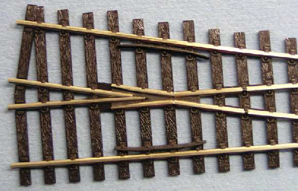
Electrofrog - Top View
Note the insulating gaps in the closure rails in the right half of the picture.


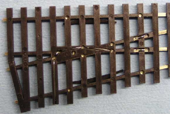
Electrofrog - Underneath View
Notice bonds between stock and closure rails in right side of view. Also, the jumpers have been cut. Also note the wire leaving the frog and dropping towards the bottom of the picture. Solder a wire to this to power route your frog.

And so I need do a little more than drill a hole for the actuator to move the blades :(
Cheers
Rod


2009 August 19

2009 August 19

 Now that I am finding the defects the shine is starting to wear off a little though!
I am starting to agree with the kiddies on Rail Page.. Maybe the Y is still No1 :D

The headlight is too bright and the light leaks through the plastic on the V/Line ones.
The Class lights go off with the headlight. That is just plain stupid!! The Class lights stay ON at night to locate a stopped locomotive. It can be fixed, but it will be a lot of extra work. I will take pictures as I do it.
My decoder has 6 functions. I will put the number lights at both ends on function 1.
The marker lights will be Function 2 and using Digitrax FX3 I can use the ditch lights feature and run them on all the time, rather than flashing or alternating. I should be able to wire two white number lights front and one red on the rear with a rear white as well, and reversing the engine changes ends for the ditch lights, so that should set the markers up nicely.
Now because I need to have two white forward and one red rear, I will have to use a diode to prevent reverse current, and connect the rear red across to the white on the other side (when running forward both whites would turn on and without the diode the red would light too. Another diode will prevent the white from feeding back as well. I think an easy circuit providing I have room to work inside the body.
I will have to cut the light tubes short and glue 0.8 mm sunny white LED's to each marker light. It is great that a member of Hobson's Bay is selling these so cheaply too.
Time will tell. Now when will I have time to do all this.. :shock: And I have 5 B Class coming to boot!
Cheers
Rod

How to write off a $300 investment Ho Ho Ho!!! :mrgreen: 


For those that want to use the fuel tank as the speaker box. Note the lid has to be snapped out. It has been glued in the corners, but releases fairly easily.
You must remove the switch and you can use the existing wires to connect to your speaker.
You should really replace the lid with an identical flat piece of styrene cut out to support the speaker. You must seal the bottom and the new lid as well as the speaker. Doing this will give an excellent result.


I missed one small problem, when I pulled the speaker away from the chassis. A small frame is glued over the attaching screw on the battery box end. This is glued to the battery box and also to the metal frame It breaks away cleanly, but it is a cow of a job to push back in with tweezers.


 blurred :( However this is the piece that fouls the battery box screw Note how it is glued in. I replaced it with difficulty and only glued it to the battery box in case of a "next time"


 To check out internal space I had to pull out all the connectors and then pull the board out of the rubber pads on the outer edges. That's all that holds it in place.:)


 The light board hides some space for a sound project.


I have three choices here. The speaker protrudes into the cab area. I can cut away the cab to allow room. Use a smaller speaker and lose the sound quality, or remove parts of the posts to the right of the speaker. The last will be my prefferred method. However I do not possess a milling machine, so I will need to do it by hand, and it also means that I have to strip the chassis bare.This job is turning into a night mare, and I am still to tackle the lights.


 The cab has the light board attached to the bottom. The cab can be prized up by using a screw driver between the roof and the cab and it is not glued in place.


The light board already uses tiny surface mount LED's


A good time to paint up your crew?


 Marker lights pull out easily
The red marker lights are white globes with the marker lenses painted red. I will simply paint the red lenses I do not want illuminated black with red over the top to keep it dark.


 The white marker lights have a light tube directed towards light board as well as a couple of protrusions that appear to have something to do with the number boards.(notice next picture)


The number boards are simply a wrap around light board and appear to be lit by the marker lights. A separate led will have to be added in here to keep the number lights on. I am thinking I can cut off the protrusions on the marker lights glue them to the number boards and attach surface mounts directly to them. The light conversion would then have cost me just 4 LED'sBased on the ease of removal of the cab, and the fact that it is not really detailed at all (and

why would you, you can not really notice the insides anyways. I think my speaker options have just changed. I will remove the back wall sufficiently to clear the small portion of the speaker that

fouls the cab, paint it (speaker) grey and no body will even know :)I guess I am not ever going to remove the sound unit, so the modification will be permanent, and apart from the obvious, the engine will retain its great looks.
Cheers
Rod

2009 August 25

I finally picked up the shop shelving that our Dahlson's Hardware store offered me, and assembled a couple of the units in the train room.
They lock together and seem to be very sturdy. I will hang boards on both sides, and run the branch line on the top level, and the Wodonga Coal Siding on the lower level with Wodonga Station on the other side.
I will probably rename it to something else, as I need this major station to generate a reason for the railway to exist. So cement, super phosphate, fuel oil and bogie exchange as per the real coal siding, and will in addition have a large grain silo to make use of all the wheat hoppers and GY's I have accumulated :shock:
I will also have a small container terminal fed by road to enable the Uncle Ben's container traffic, and create a reason to have some Auscision 4 wheel wagons.
In addition the Wodonga Station will also have two oil sidings, a freight shed and a large stock race.
I must take some pictures tomorrow of this shelving. I think it will do a great job supporting the centre modules. Oh and I am sick again, seems the cough is back, had a feeling the penicillin tablets ran out a day or two too early last time.
Cheers
Rod

2009 August 26

 I have 8 sections of this shelving, enough to reach the far end. I will use the trays at the bottom to further stabilise the structure, by loading boxes of stored items here. Not that it needs it.


The old layout that I am restoring will be used to form the branch line on the top level.

and I will need to construct a support on the end to hold up the narrow curve over the trestle bridge that joins the front station to the back station (Trentham)
Cheers
Rod

2009 September 2

One of my biggest problems is the mess I get in ... for the want of a good local hobby shop :(
There is an old, poetic parable that goes something like this:

For want of a nail the shoe was lost.

For want of a shoe the horse was lost.

For want of a horse the rider was lost.

For want of a rider the battle was lost.

For want of a battle the kingdom was lost.

And all for the want of a horseshoe nail.

you have to marvel at the simplicity of these old tales and how so few words can contain so much wisdom. :)

The meaning behind this tale is that, "The Devil is in the details." This applies to just about everything I can think of that I have experienced thus far in my life and certainly applies to my model railway projects!
At the moment I have at least 8 mail orders not yet filled. That means I have at least 8 projects that I cannot finish waiting on parts. It seems silly to reassemble an engine, when you can carefully place all the parts in the box and stand it aside on the work bench. However with limited space you soon find yourself unable to start a new project, because of this lack of space.

After spending many hours on the A Class project and arriving almost at the end, in fact I was soldering up the last few wires, after test fitting and finding it it all went back together with the modified lighting and the Loksound unit and speaker fitted.
I noticed that a red marker light was missing, and it was no where I can find. It had broken off as I pressed the markers back into place. My FIRST bit of Damage in the A Class project. I found some fibre optic material that would fit the ole in the nose, retrieved the red paint and tried to melt the lenses in the end of the fibre. The Duratech was not melting the fibre. So I plugged the 15 watt Wella iron in and waited for it to heat up. I bunched the wires together and taped them neatly out of the way in the mech, and ran a final test of the wiring. I then picked up the iron to work on the fibre lenses.
The bloody telephone rang. It was rather late, so rather than turn the iron off as I normally do. I placed it on the work bench and answered the phone. Thinking I could get rid of this unkind person ringing at this time of night, I find it is my brother, and he needs a shoulder to repeat things I have heard before... but I do the right thing. 40 minutes later I hang up, and where was I?
Oh yes the A Class :D
I swing around and there is the soldering iron, which has travelled a meter across a cluttered bench laying up against the nose of A68 :shock: Its stuffed and all the work is down the drain. I turned off the power closed the door, and have not been near a model till tonight, so it has taken 5 days and the arrival of two parcels of parts to get me back in here again.
How unkind is life. Granted my brother needed me, but how bloody unkind is life!
I have sent of a letter to Peter Wilkes , and just maybe he has a faulty mech returned, and I might save full price on a replacement . But I am absolutely gutted. :cry:
Cheers
Rod

2009 September 11

Ha Ha!
I am feeling better today :D
Jaimie from Auscision rang me today and he has found me a new A78 shell to replace the damaged one :D

Seems that somebody returned it because it was delivered without number plates. I used a sharp knife and removed the number plates off the damaged shell, and now I wait patiently for the replacement.
And publicly I shout from the roof tops.
The boys from  Auscision  are jolly good fellows!!
Cheers
Rod


2009 August 5

 2009 August 5


Feeling better! Had a visitor this weekend, and he pulled me out of my sorry state and we sat down and started some kit building. Got the Z Van cut out and ready for a interior paint so I can glue it together after glazing it.


But we did get 7 GY's together with 13 to go. Intend to get all 20 ready for a warm "paint" day. Now waiting for the additional brake kits from SEM, as the Melbourne shops we visited did not have them in stock. The tarps are a new product produced by Rob Carpenter of N scale fame. Very nice indeed!
Hopefully the track stuff I ordered from the States (You guessed it nil stock in Australia) will arrive this week as well. Then I can get some track down in the Train shed.
Well at least something got done :roll:
Rod


2009 August 7

Found this in storage. Actually forgot that I owned one.
Scaleways made a very limited run of these many years ago. I also found 13 Lima Aurora coaches and 13 under bodies and 13 sets of bogies. So it looks like I have another project to add to a very long list.


Cheers
Rod


2009 August 17

sih!!
More distractions ....


Sorry I darkened the room without a flash to capture the lighting. Did not really work did it?

Some may not have seen my warnings about how to open the A.
So I repeat it here :D

WARNING!!!!
First thing READ INSTRUCTIONS!!!!
A lot of you are going to break these as they are fragile...

Instructions say remove the couplers...but...
The screws holding the couplers on my two A Class appear to have been glued in
(I will post a picture) Use the right size screw driver and careful you don't
crush the body as you struggle to remove these long screws!!

you MUST NOT lay it on its roof because the fans whistles aerials are going to
break.
You must not lay it on its side, because you will break off the mirrors and underbody detail.
and the tank is prototypically gapped It will SNAP OFF.

Instructions say the body will slip off easily IT DOES NOT !!

almost 90 minutes later and both bodies are still firmly attached.

I have no loose parts yet ;) .. just!! BUT PLEASE BE CAREFUL !!!


Part 2

First Apologies for those who use other Forums (cross posted)


removed screws were certainly tight. Is that glue on the threads?


 stuffed around for about 90 minutes
Directions forget to tell you that their are 4 heavy lugs holding the body and
chassis together.


 Auscision are to be congratulated for the addition of an exploded diagram and
directions.


The heavy lugs are shown on body look above the white plugs.
You can just see the slots they fit into on the chassis, picture bottom.


NMRA 8 pin connection, Pin 1 clearly marked after removing the DC convertor
plug.


 NMRA Convertor plug and the nifty Digitrax DH165IP full function DCC chip.
Carefully find the tiny square circuit board solder tab on the opposite side to
the pins.
the solder tabs are all round except for PIN 1 (it is the bottom RH pin in the
picture)
line it up with pin 1 on the locomotive light board, carefully push it in
ensuring all pins enter holes provided.


The square pin can be seen here I think
This is a truly DCC plug and go!!
It works that easily :>)))


 Very carefully push the body on to the chassis making sure it is pushed down
firmly and level
check that wires are clear and that the locking lugs clip into chassis.

And that all their is to it!!


First model took about 2 hours.
And armed with the knowledge above, I converted three more in 40 minutes.
Ha!! and no damage!!
I am feeling pretty happy.....

Now where's those B Class

Sound will be the next thing to tackle. As I thought Auscision are going to have
to brought before the headmaster and given a caneing!!
The only way to fit sound is to cut great holes in the chassis and I think I
will let somebody else be the first to try that one.
Possibly by tearing out the light board and replacing it with hard wiring, or a
tsunami at card?
But this time round, I have no idea where a speaker could be mounted.
Perhaps a small one in the tank?

Cheers
Rod

2009 August 18 

Hmmm, looks like I'll be getting either an FA/FV one or a VLP one at AMRA... Those just look SWEET! And thanks for the tips Rod, will certainly be handy when the couplers swap, and the DCC decoder goes in :)
Zec
Yes I near shat myself when first the couplers would not come out, and then the body was stuck down good. I thought it had been glued on!
Their is very little room to jam a knife down, and anyway they don't show where the lugs are.
I felt the body move when I eased it out with a jewellers driver, worked out where the lugs were, grit my teeth and pulled it apart  :cry:

Once I could see what was happening, all was well And glad to help Zec!
However after my post a couple mates showed up with another 4 models to convert  :lol:
Did them all in a few minutes and sold three decoders to boot.
The Digitrax DH165IP is the one to use. It also can run a bug sound chip in the future.
Cheers
Rod