G'day comtrain,
It's great to see you back at work, Rod, and that is what I would call an 'elegant' solution to the problem you had, if a somewhat 'over engineered' one. I am also pleased to see that you did not make the unforgivable error most people make of "neglecting" to place the girders 'correctly'. I do, however see a 'flaw' (or should that be "floor") in your 'cunning plan'...
...9 out of 10 of the bridges of that design used throughout the North east were of the so-called "Open Deck" variety. That is, the sleepers effectively sat on top of the girders with nothing but L-girder frames (mostly of 4"x4" profile) to support the span girders and to keep them stable (relative to each other), so there was nothing to prevent any objects from falling through the bridge into the creek below, This also made the decks very 'see through'. Those few that were provided with so-called "Ballasted Decks" (which I suppose is the type you are trying to model, here, since you have clearly incorporated kerbs into your construction and only ballasted deck bridges would have kerbs) had the transverse timber planks (mostly 6"x3" timbers) placed directly in top of the steel spans and the sleepers on top of them. The 6"x6" kerbs would then retain the ballast placed on the deck to provide the usual 'support' for the track (which, on the Open Deck bridges was replaced with bolts securing the sleepers in place), Ballasted Decks, by the way would not require 'guard rails'...
...incidentally, although a number of these bridges were, in more recent times, painted in Oxide Red (as you suggest), for the most part they were originally painted either in a nondescript Grey or a Metallic Silver...
...carry on...
Jerker {:)}
Thanks Gary
Yeah I knew they were going to be wrong, but much better than the strips of ply wood presently occupying the crossings
Between Wangarratta and Wodonga almost all of the x BG bridges were ballasted, and the SG bridges beside them were open deck.
So I decided to model the tracks that way
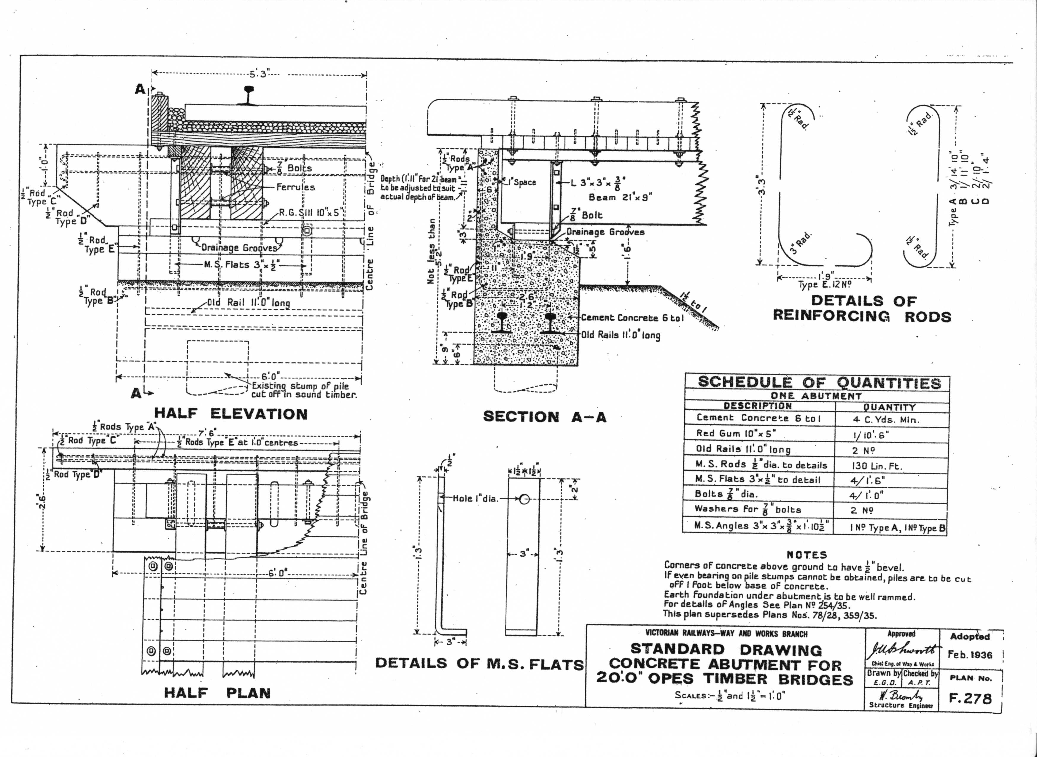
All I need now is to work out how to replicate the abutments. You have not seen the brick abutment drawings by any chance?
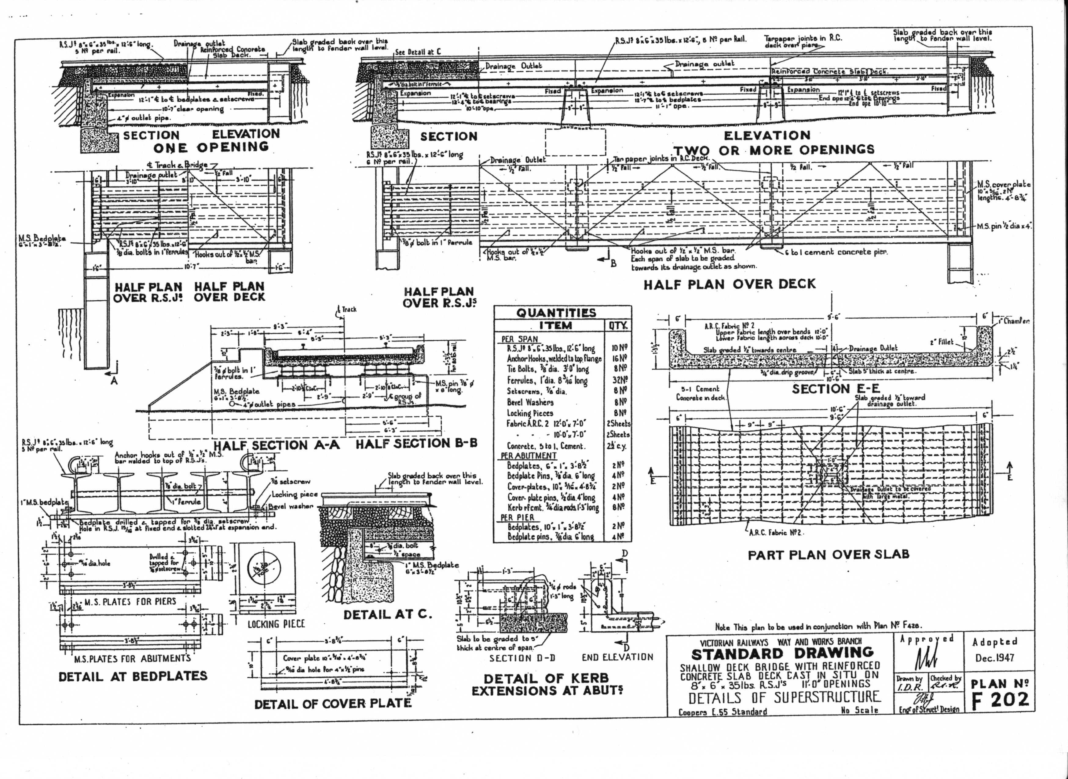
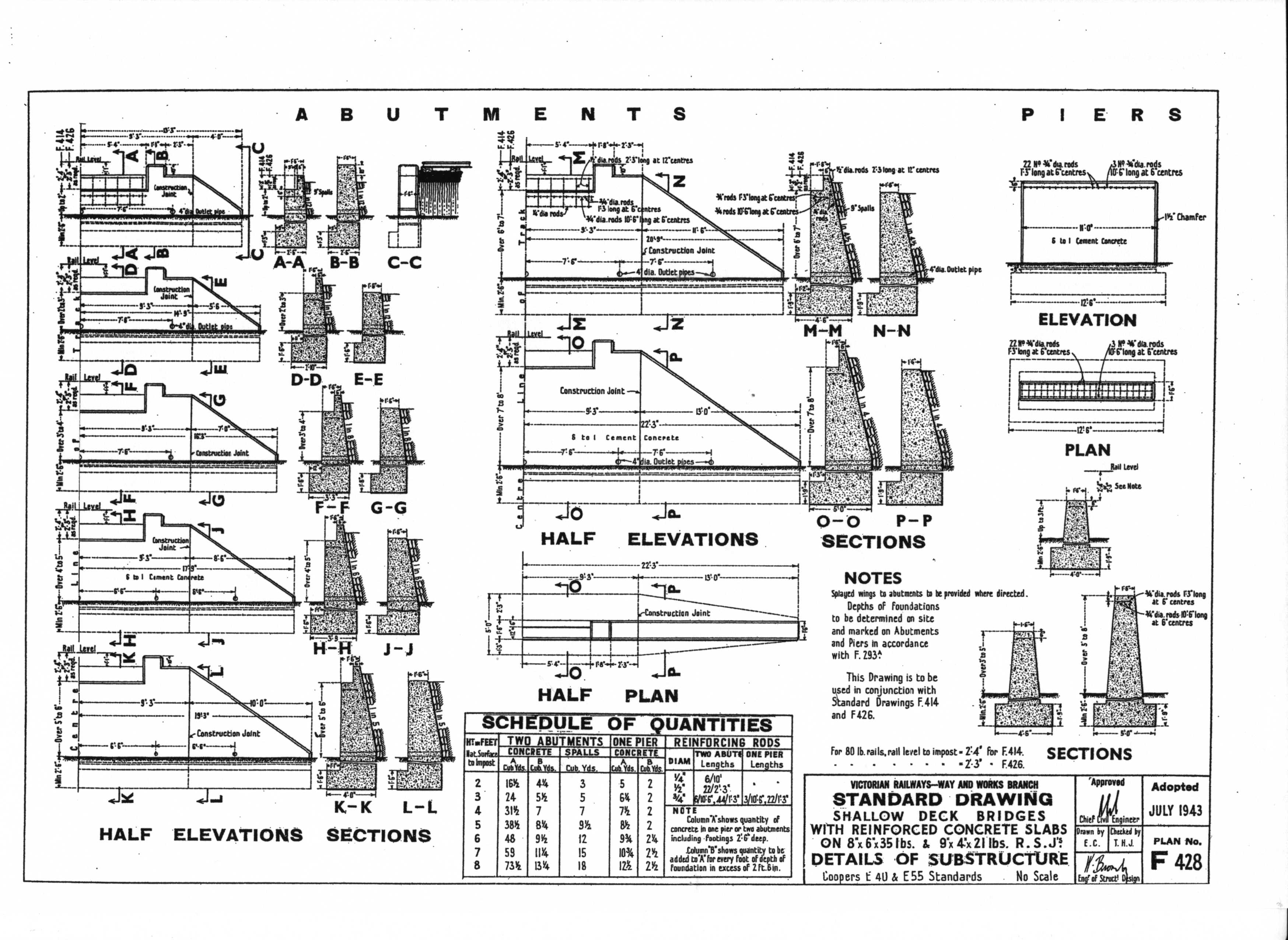
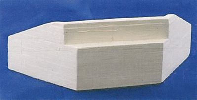
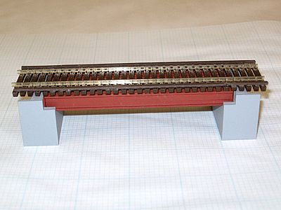
Mark provides this concrete bridge (ballasted) which looks very much like one US Kit I found. All these bridges use 4 or more I beams instead of two reinforced cast panels as mine is.
Shallow Deck Bridge 01
Concrete Abutment
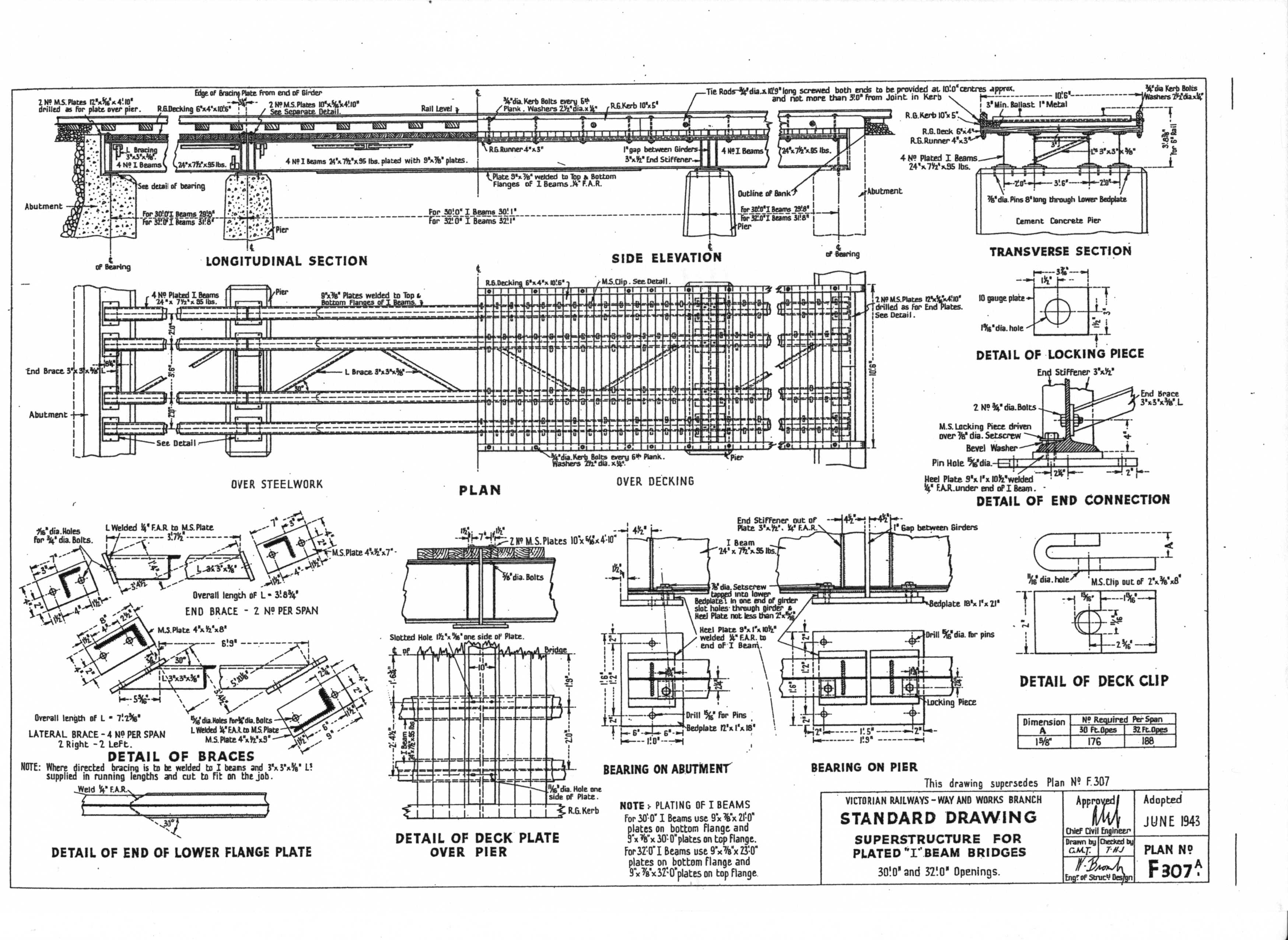
plated I beam bridge
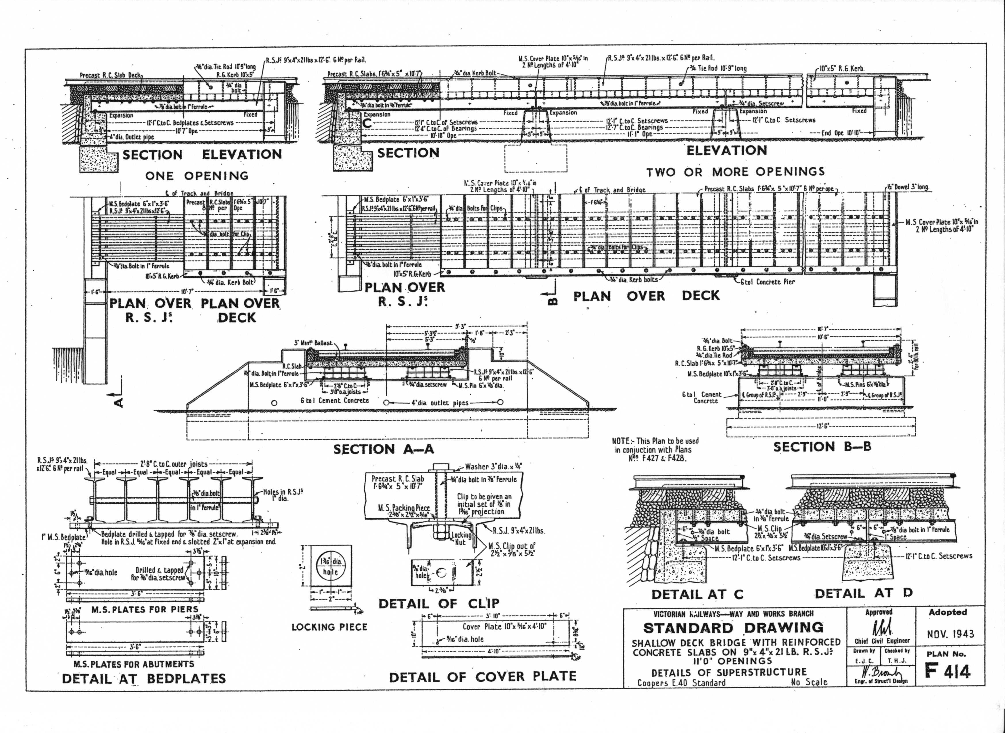
Shallow Deck bridge 02
Skeletel type
Skeletel type with RSJ
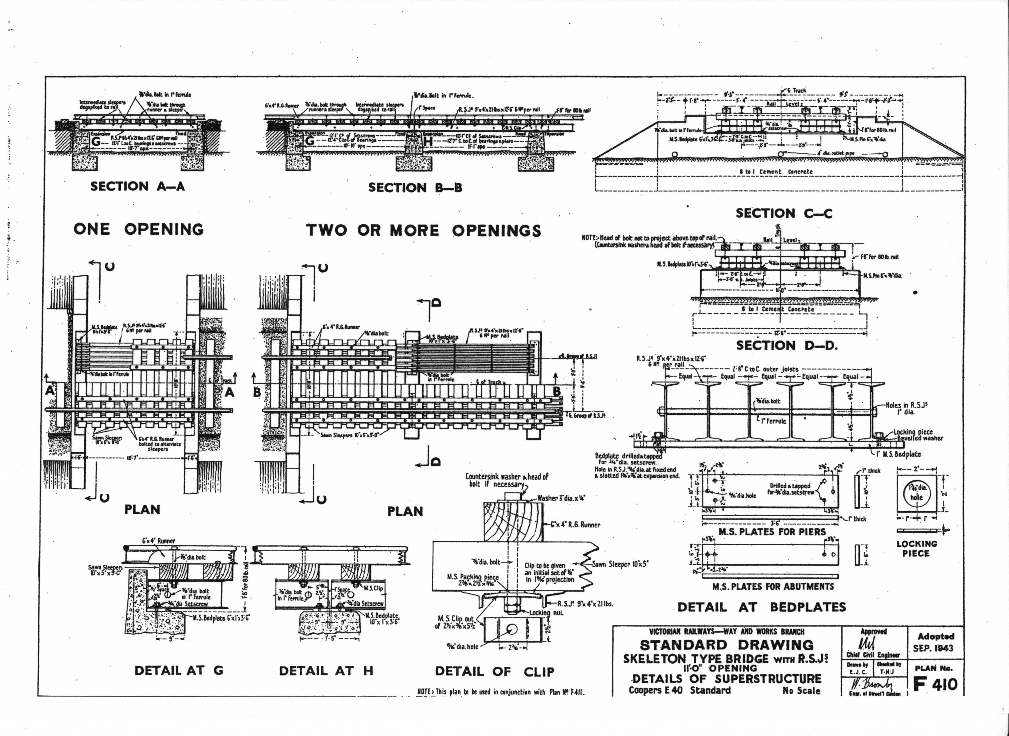
concrete abutments
Skeletel type with RSJ Abutments
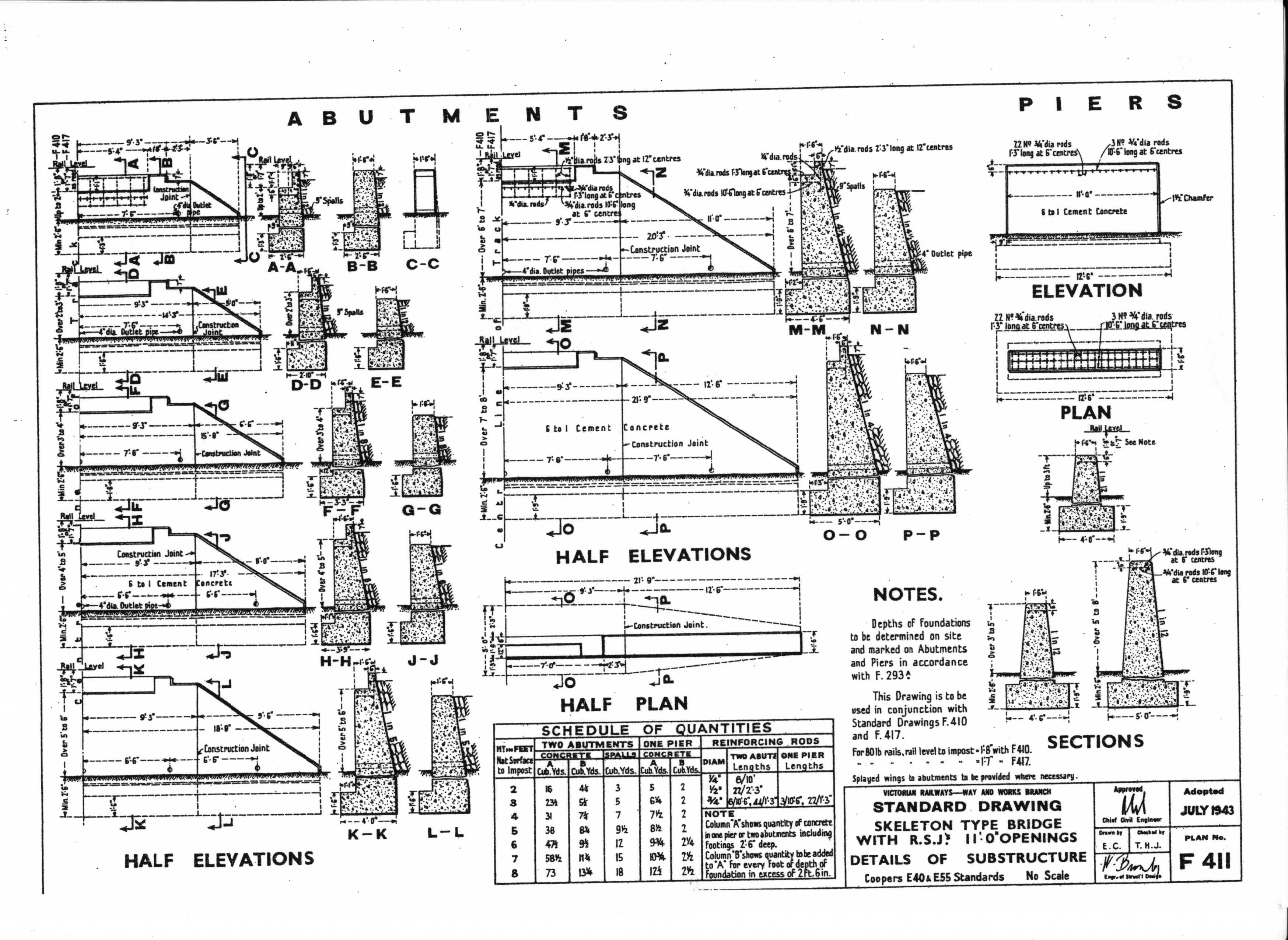
Another skeletel This time using cross braced large I Beams
Skeletal type using cross braced large beams
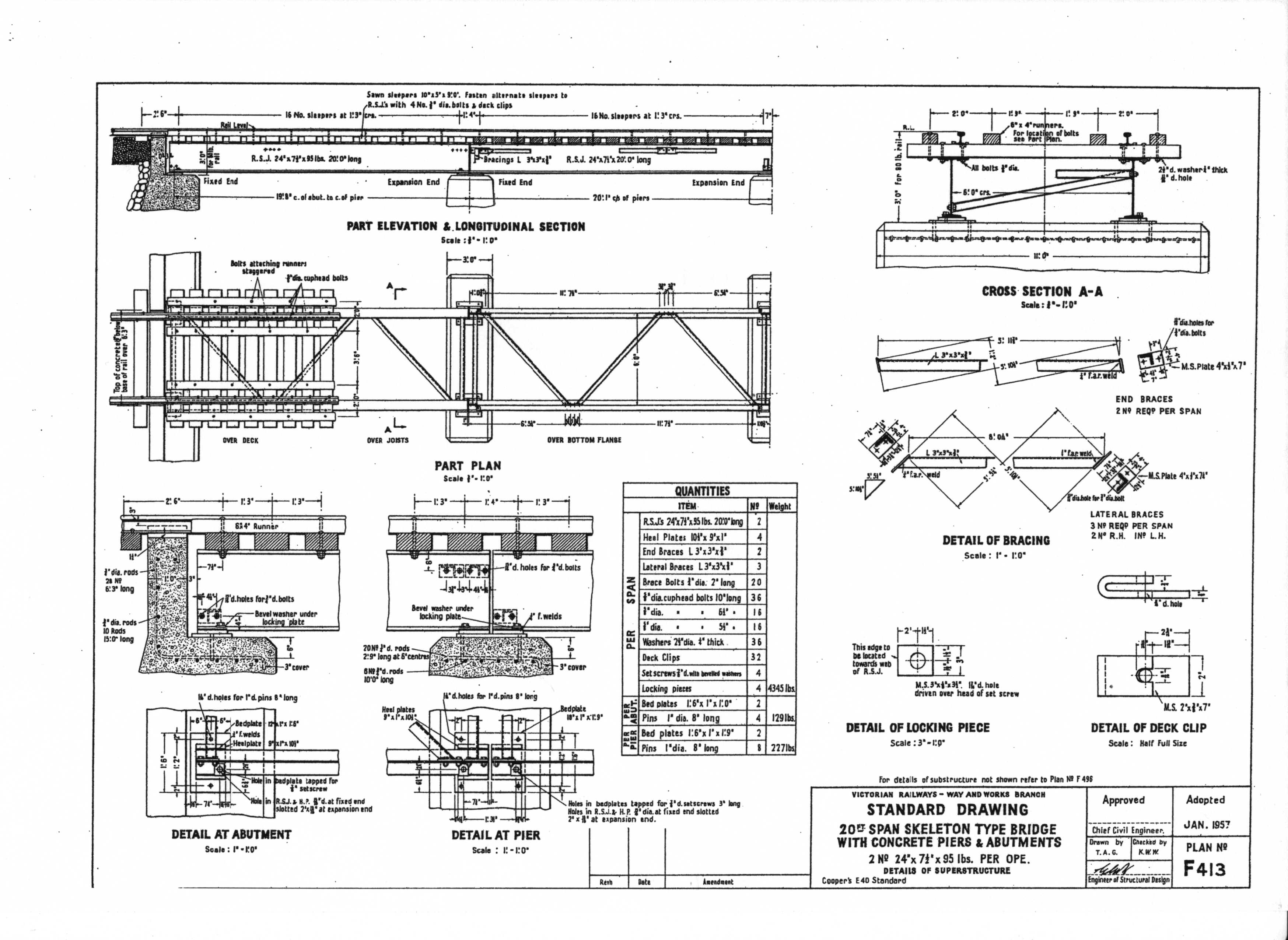
Skeletal type 11 foot openings
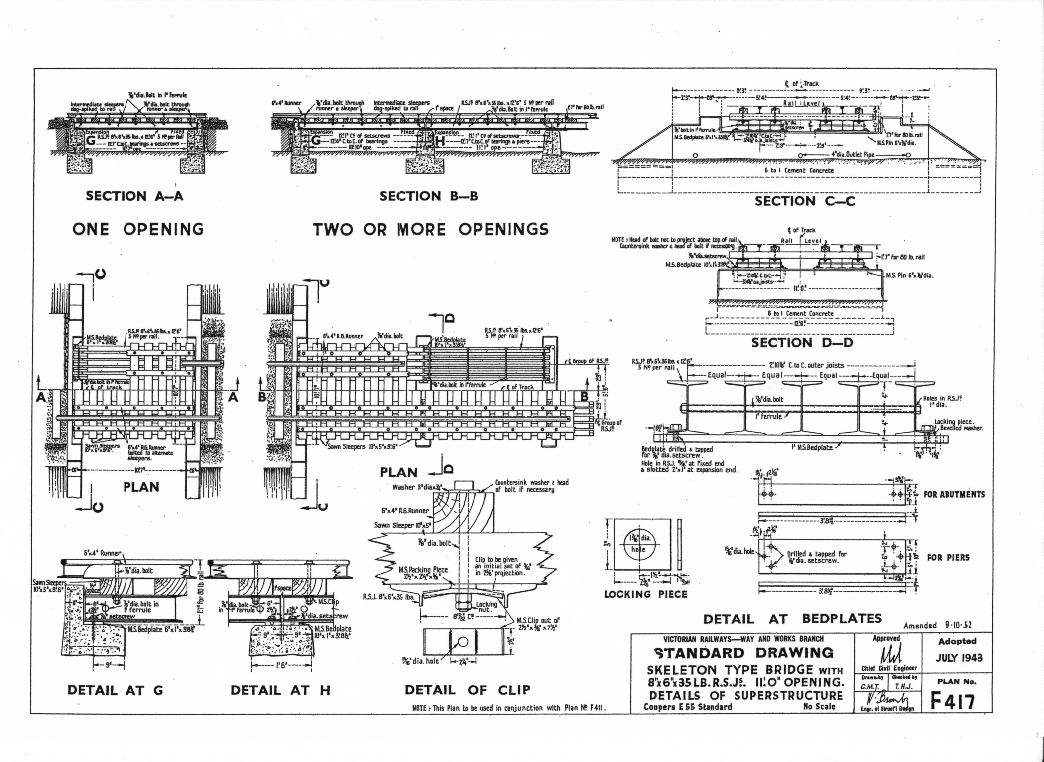
This looks like the concrete abutments?
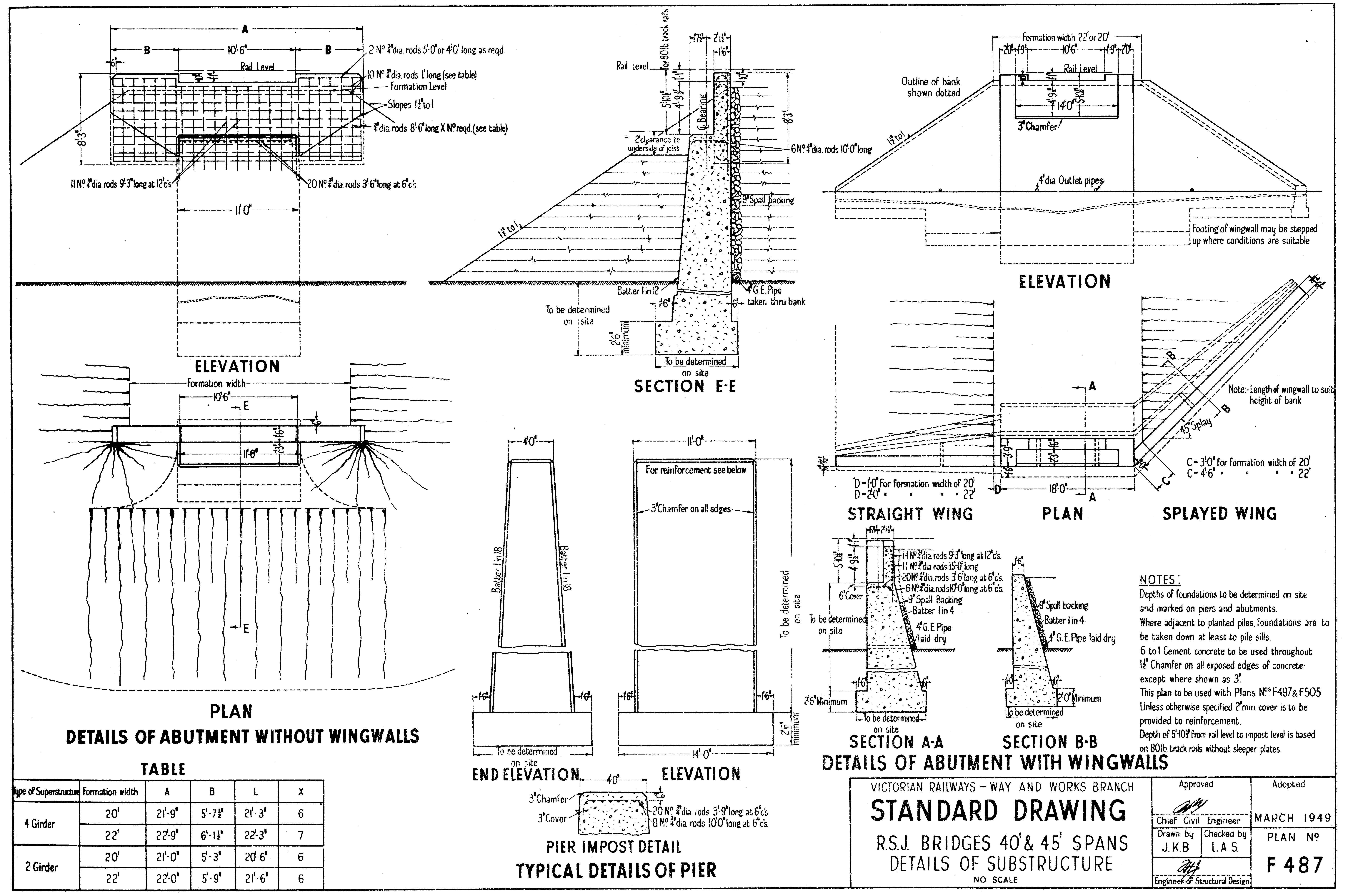
Shallow deck abutments
wingwalls
Wing Walls
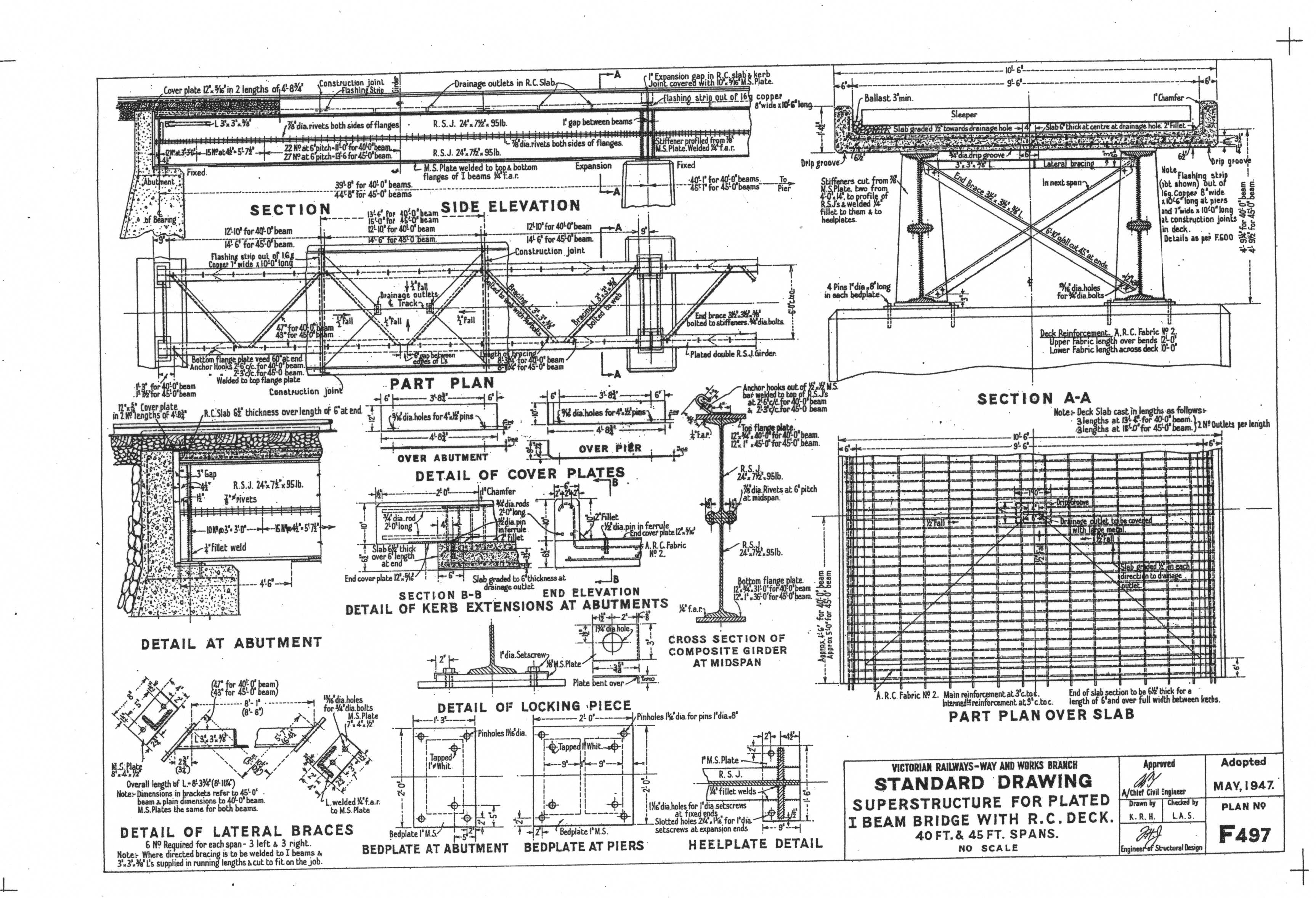
Similar but has concrete and ballasted decks
plated I Beam and reinforced concrete deck
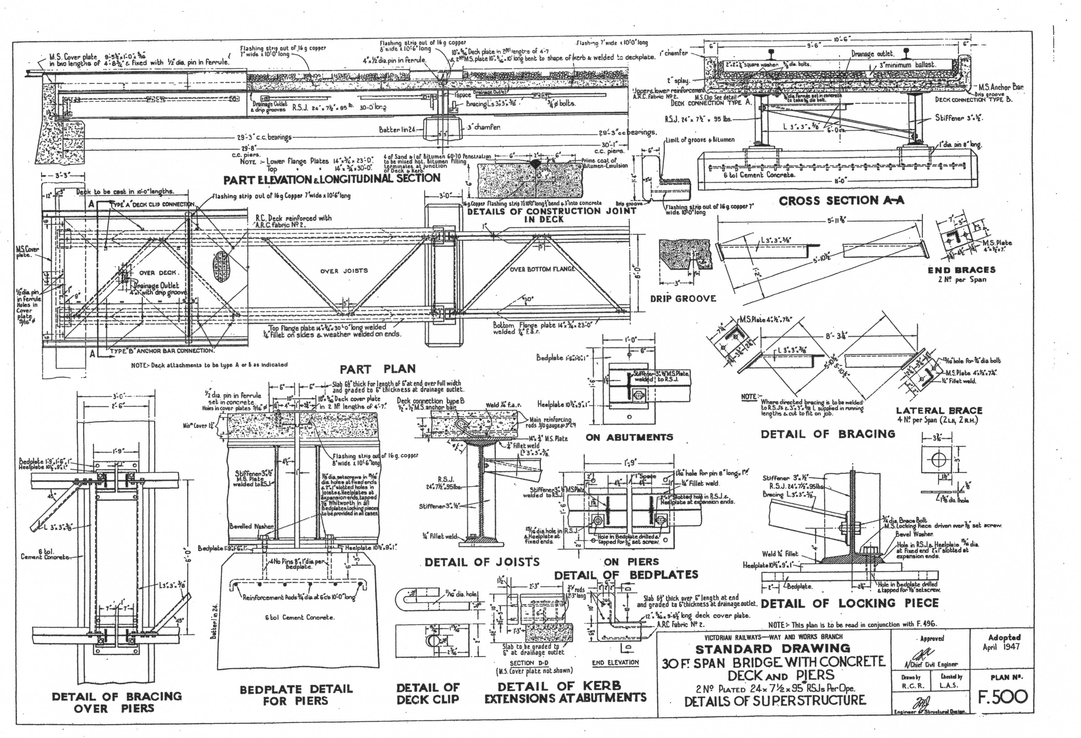
It looks like the spans are 30foot I might have to trick mine to look like two spans
30 foot Girder bridge
Its never ending
Going to use some of these for the SG

http://www.hobbylinc.com/htm/ada/ada7784.htm
http://www.hobbylinc.com/htm/aim/aim552.htm

2012 November 11 Rememberence Day
Sat/Sun
After 11.00 AM and after doing my duty to lost comrades...............
I watched a movie. Has anybody watched Disney's "Brave"? Another wonderful film, that I will definitely add to my collection as soon as they are available
So that left with me only a short time to do something positive with the "Railway" It was decided that as the brain had been ticking over for a month or two...

The first shot shows one final check of the levels before fixing new cross pieces in place that will allow me to install a slight camber to the curve.

I settled on 2.5 degrees, which was almost exactly two widths of Masonite packing strips
The yellow level shows dead level sideways (Gradient is 1.5% climbing on the roadbed)

Cut the post before I thought about it. Packing is screwed and glued in place
No


Strengthening strips glued under the roadbed.

The roadbed was then cut into the 5 ply with the router, and glued in place. Will screw it down for security as well. Should have cut deeper, not sure how I got the depth wrong?Will sand the leading edge down before laying any track.

Once the curve is fixed down. I have to go back to this side and install cross braces to the 5 ply panels to add extra strength and make the joins in the ply fit exactly. (Something I just made more difficult by getting ahead of myself
Cheers
Rod
edit Pictures blown up sometimes show up things I did not notice
Like the picture immediately above which very obviously has the wrong angle bracket installed
And picture 5 above which shows the glued 5 ply joins...aren't ??
ok added to the list for another day!
2012 November 10 Saturday
Jerker wrote:
G'day comtrain,
Indeed, Rod, most of the bridges along the line used a span length of about 30 feet ...
[See Gary's full post above]
...one thing I would recommend you do, is to remove those wooden 'kerbs' you have provided on the bridge you created above and replace them with styrene 'strips' at a scale 6" x 8" and attach these to the SIDE/edges of the existing deck (rather than on top of the the sleepers as you have them, now), with the bottom of the strip 'level' with the top of the girders, which I think will look much better...
Jerker {:)}
2012 November 10 Saturday
Thank you Gary
All taken on board
Thank you for your input :) . I have had near 50,000 looks and I hoped to get a lot more input
But I understand that people cannot post here without joining up, and some are reluctant to join just to post.
Wish I could find a way to get input from everybody. Yours is invaluable, and I know I am missing out on a lot of good stuff
Anyway a trip to Barnawatha produced these pictures, showing me exactly what you were telling.
Ignore the galvanised edges applied to the old BG bridge and that's what you suggested, and it will make it look great. Thanks, and here are the pictures which others might find useful as well.
Cheers
Rod
SG Skeletel Bridge Barnawatha


Top views both bridges


2012 November 13
Aaron™ wrote:
I wonder why they went through the trouble of putting one set of concrete sleepers and leave the other side wooden.
They could have always put new wooden sleepers on the bridge as that's what it was designed for, even the bridges on the Geelong line had new wooden sleepers fitted because of the work that would need to be done for concrete.
They could have always put new wooden sleepers on the bridge as that's what it was designed for, even the bridges on the Geelong line had new wooden sleepers fitted because of the work that would need to be done for concrete.
Hi Aaron,
Not sure what you are getting at?
These bridges are constructed in different ways. Putting concrete sleeper on a steel deck probably would not work. As the concrete would need to be drilled out to be attached. That would probably destroy much of the reinforcing steel included in the pour, or entail a much more expensive concrete sleeper construction technique?
And then you would need to find a way to insulate the train from these hard surfaces, or you would have a really bad hammer effect as the train operated on such an unforgiving hard surface!
The wood sleepers on the sg bridges are insulating the train from the bridge.
(hmm I know what I mean, just not expressing it properly
The old bg bridge uses the timber decking and the ballast to "soften" up the impacts of heavy trains.
I suspect that to convert a skeletal to a ballasted, would require a concrete or galvanized steel pan be constructed to carry the ballast
Now I am not sure which bridge they would build today, but suspect that the skeletal version is the one they would use. Noticed on the Darwin line they built skeletal with wooden sleeper? That I did not notice but strongly suggest they did. But I guess rubber pads under a concrete sleeper would fix the problem too, at a much higher cost?
Cheers
Rod
2012 December 13 Monday
What a great day! Sunny! cool walking under the trees in our lane and got 5 k's in, in just over an hour.
Also managed to (almost) finish the High Street curve
About 2.5 degree cant is almost impossible to see. Might look better with a train on it

Check the cross levels and found them to be flat.

hmm apart from reminding me I need (half) a haircut, this shot was supposed to show the two clamps, one on either side. The outside clamp to keep the road bed in contact with the leg, to maintain the gradient. The inner one is then squeezed down to hold the cant, whilst I screw the cross piece home.


ah.. there you go, just like that! And the bubble is sitting dead centre

So next step was to cut out the 38 x 19 pine spines and glue and clamp them in place. Then when dry put a couple of wood screws in each spine and remove the clamps.


And here is the reason, not much got done today, and this job was not signed off.
This is my two year old Ryobi 1250 ERT Plunge Router. I bought it when I needed to do some work with Roger Lloyd a few years ago, and we used it for 20 minutes. Did a good job. It sat on the floor up until a week ago, never being used again.
I then routed a step in my 5 ply, and all went smoothly. However today it simply stopped half way through a job, and I have not been able to start again.
What a waste of money, Out of Warranty and it is cheaper to buy a new one, rather than pay cartage to Melbourne and return plus repairs.
Ask me what I think of RYOBI and Bunnings!! Grrr!!
Anyway
Cheers
Rod
(2012) 1945 November 16th Friday
Well this old bastard was in the train room again, alas no new trains on this day, and I guess everyone knows that I don't NEED any more trains

So first thing was to sand down the ramps and also place in position three extra cross pieces to support the first sheet of ply. Wasted an hour or so trying to create a poster print on my little A4 printer to create a large signal diagram to help layout the tracks.

So much for laying some track on the curve today as planned
The 46" and 44 inch radius curves must start 6 inches closer to the back drop, otherwise I lose two extra roads in the siding

Love these new "Fast Tracks" templates They really help sort out the problems and make setting curves up on flexible tracks a cinch. With a short straight in the system, it all fits in nicely. Now I will have to cut out the mistake and relay the track bed, before even thinking about track

So just standing back a little
Cheers
Rod Young
FAST TRACKS SWEEP STIX
2012 November 16 Friday (continues)
Ah, Felt Guilty because I walked away from another blunder

Clamped the two bits together. Then when they were (almost) right, I cut through with the renovator screwed and glued it to the spine after sorting out the other end.

Used the cheap $50 router that replaced the much more expensive Ryobi piece of crap to carve out a new place for the track bed to sit. screwed and glued in place, used the sanding disk on the renovator to quickly smooth out the join and puttied up the gaps
Screwed it all back down to the spline, strengthened the join at the other end, all in less than 40 minutes.... Now I think I will spend tomorrow marking out the track, and maybe, even laying some
Gee I reached 50,000 looks on my birthday
Hope you guys are enjoying my trials and tribulations (and not just laughing at me)
Although all's good as long as we are all enjoying ourselves Ha Ha
Thanks for looking
Rod
No comments:
Post a Comment
All comments and suggestions from like minded individuals always welcomed. Help make this railway better :D